Mixing It Up
- Published: December 01, 2003, By James M. Wheeler, Wheeler Consulting
Analyze your mixing process to root out the cause of poor performance.
If inadequate mixing is the suspected cause of product defects, proper analysis of the process will help pinpoint the root cause. Following are the suggested steps to take to determine the problem.
- Measure the mixer performance
- Develop a functional analysis of the mixing process
- Assure the process is in control
- Evaluate opportunities to improve the mixing process.
Measuring Mixer Performance
Measurement of performance begins with setting specifications for the mixer output. Specifications are based upon fitness for use in the next process step or, in the case of a finished product, by the end-user. A specification comprises an aim value, a lower limit, and an upper limit.
Specifications quantify the requirements for a mixing process. Examples include:
- Concentration of all chemical species
- Temperature of mixed solution
- Completeness of chemical reactions
- Completeness of physical reactions such as dissolution of solids, bubble size, or dispersion droplet size.
Developing a Functional Analysis
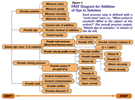
Identification of key dependent variables is facilitated by displaying the process functional relationships in a diagram starting with the outputs on the left side and adding the next level of input to the right. This method is known as the “Functional Analysis System Technique” or FAST (1,2).

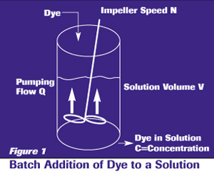
To illustrate, consider the simple mixing process of adding a dye to a solution as depicted in Figure 1. A batch mixing tank is charged with a measured mass of solution; a measured mass of dye is added, and the mixer operated for a specified blend time.
A FAST diagram for this process is shown in Figure 2. Each process step is defined with a “verb-noun” pair, i.e., “What action is needed? — What is the object of the action?” The overall process output, “Obtain dye in solution,” is shown at the far left. Then each step of the process is displayed in hierarchical order until all of the process inputs are identified.
Thus, the diagram moves from “why” to “how” as read from left to right. For each process step, specifications on the output are required.
By displaying each variable in the proper sequence and relationship, a FAST diagram provides a clear picture of the process mechanics. This picture, coupled with an understanding of the process operation, (e.g., set points), aids in distinguishing between independent and dependent variables. The most important dependent variables should be control-charted to monitor the process.

Example: Dependent Variables for Dye Addition
N, the mixer speed in rpm
P, the mixer power consumed, proportional to N3D5. (3)
Re, the mixing Reynolds Number = D2N?/µ
Where
D = impeller diameter
? = solution density
µ = solution viscosity
All other variables on the FAST diagram are independent. They are established by the design of the tank, the mixer, the environment, and the operational inputs.
Assure the Process Is in Control
A control chart should be maintained on the most important product features of the process output. In the process shown in Figure 1, the dye concentration, measured after the target blend time, should be charted. In addition, key process dependent variables should be control-charted in order to monitor the “voice of the process.” Charting the key dependent process variables permits one to understand the potential causes when the product features go out of control or out of specification.
From the FAST diagram, it is apparent the candidate dependent variables are N, P, and Re. Note that P and Re are functions of N. Thus, N is the only variable necessary to monitor.
A control chart showing the value of N obtained for each batch of solution prepared will indicate the process variability. Control limits for N are calculated based upon the process common cause variability as measured by its standard deviation (4,5).
Using these control limits, the control chart indicates whether the process is in control, i.e., no special causes of variability are occurring.
If the process is in control but fails to meet the target defect rate in the process output, the process is not sufficiently capable. To lower the defect rate, the mixing process itself must be improved.

Evaluate Improvement Opportunities
Selection of Impeller Type — A wide variety of impeller designs is available. Choosing the best design depends upon the type of mixing needed to achieve the desired process result. Mixing processes generally fall into one of two types: low shear and high shear. The key mixing parameters of each are summarized in Table I.
The particle sizes, droplets, or bubble diameters being mixed determine “Scale of Mixing.”

Figure 3 shows a decision tree to guide impeller selection. Low shear requirements typically use axial flow impellers, while high shear applications are best accomplished with the use of radial or radial-axial flow combination impellers. Figure 4 shows a typical axial flow impeller while Figure 5 displays two types of radial flow impellers.

Location of Impeller — Optimal impeller location depends upon factors such as:
- Fluid viscosity
- Type of mixing application
- Type of tank shape
- Presence of baffles
- Ratio of impeller diameter to tank diameter (? is common).
No single design is recommended for all applications. Best practices provide the following guidelines:
- In an unbaffled tank, the impeller should be located off-center and in some cases, with the shaft at an angle of 10-15 deg to avoid swirling and vortices. (3,6)
- In a baffled tank, the impeller usually is centered.
- For blending and maintaining suspensions, the impeller should be located to minimize the power consumption while achieving the required mixing action. Experimentation is recommended to determine the minimal power-consuming location.
Use of Baffles — For low-viscosity fluids, four baffles are typical with each baffle 1/12 of the tank diameter to prevent swirling and vortices. (3)
For high viscosities (5-10 Pa-sec) the tendency to swirl decreases and the baffle's size is reduced to 1/24 of the tank diameter, located halfway between the impeller and the tank wall. (3)
In-line vs. Tank Mixing — If the components are available continuously and the mixed solution is consumed by the next process step on a steady-state basis, in-line mixing offers a number of advantages over tank mixing:
- Process control — the mixed output can be monitored continuously for concentration, temperature, bubble content, etc. Feedback loops can be used to adjust inputs to obtain precise control.
- Liquid hold-up is reduced.
- Concentration and temperature uniformity is improved.
- Chemical reactions are controlled when reactive components are mixed. Examples include polymerization and hardening agents.
Two types of in-line mixers are available: static and dynamic. A static in-line mixer provides a tortuous path through fixed blades or chambers, whereas a dynamic in-line mixer utilizes powered impellers to achieve mixing. A comparison of features is summarized in Table II.

Selection of Mixers and Impellers — The World Wide Web is an excellent resource for investigating mixing equipment and manufacturers: industrialmixers.com provides a brief description and Web site link to each of nearly 100 international companies that provide mixing equipment; also see Thomas Register at thomasregister.com. Many mixing company Web sites also provide a selection guide to help the user identify the proper equipment.
To save time and money, improving mixer performance should be based upon an understanding of the root cause of poor performance: Ask the following questions:
- Are specifications on the mixer output clearly defined?
- Are the mixer output and key dependent variables in Statistical Process Control?
If the process is in control and the defect rate remains above the target value, then the mixing process itself must be improved. Impeller location and power input can be investigated with the current equipment. Impeller and/or tank design changes may be required to achieve the target performance level. If components are available on a continuous basis, in-line mixing offers a number of advantages and should be considered as an alternative to traditional tank mixing.
If you need technical assistance, a consultant can help you analyze your mixer performance and recommend equipment changes. The Association of Industrial Metallizers, Coaters and Laminators (AIMCAL) provides a list of consultants on its Web site, aimcal.org.
Jim Wheeler is a consultant to the coating industry. His expertise includes selection of coating processes, delivery systems design, coating fluid properties, and Six Sigma process control methodology. He retired from a 30-year career at Eastman Kodak where he served for nine years as the company's director of coating technology. In addition to consulting, Jim is the co-founder of WESEECO LLC, a company dedicated to the development and distribution of computer-based courses in fundamental engineering. Jim holds a Ph.D. in chemical engineering from the Univ. of Minnesota and is a registered professional engineer. He serves as a technical consultant for AIMCAL. He may be reached at 239/732-6505; This email address is being protected from spambots. You need JavaScript enabled to view it..
This article, along with future articles by other authors, is provided as a cooperative effort between PFFC and AIMCAL. Authors contribute to AIMCAL's technical and education offerings, which include the association's Fall Technical Conference, Summer School, and Ask AIMCAL.
The views and opinions expressed in Technical Reports are those of the author(s), not those of the editors of PFFC. Please address comments to author(s).
References
- Wheeler, J.M. 2002. “Getting Started: Six Sigma Process Control of Chemical Processes.” Chem. Engr. Prog. Vol. 98, No. 6.
- Miles, L.D. 1972. Techniques of Value Engineering. New York: McGraw-Hill.
- Oldshue, J.Y. 2002. Encyclopedia of Science and Technology, 3rd ed., Vol. 6, Academic Press.
- Brassard, M. and D. Ritter. 2000. The Memory Jogger II. ISBN 0-385-49437-8. Salem: GOAL/QPC.
- Wheeler, Donald J. 1993. Understanding Variation, The Key to Managing Chaos. ISBN 0-945320-35-3. Knoxville: SPC Press.
- Oldshue, J.Y. 1983. Fluid Mixing Technology. ISBN 0-07-047685-3. New York: McGraw-Hill.


