


Winding: Part 2
- Published: December 19, 2022
Document Your Wound Roll Structure
By Neal Michal, Principal, Converting Expert, LLC
This is Part 2 in a five-part series regarding winding, with this month’s focus on documenting your wound roll structure.
Last time we discussed the two types of wound roll structures that are possible. A “soft roll” will feature an S shaped interlayer pressure with a U-shaped MD strain profile. A “hard roll” will feature a peak interlayer pressure at the core that will decay toward the outside of the roll. The stored MD strain will look like a Nike swoosh.
You can characterize your wound roll structure by documenting either interlayer pressure or stored MD strain.
Document Interlayer Pressure
There are two proven ways to measure interlayer pressure:
- Wind in pull tabs
- Reverse pull tabs
When possible, you can wind tabs into the building roll. This can be very dangerous so one must be careful when placing the tabs into the building roll. Once the tabs are wound into the roll use a handheld load cell to measure the force to remove the tab. This test is generally reserved for a slow speed pilot line application.
A much safer method is to use a “reverse pull tab” technique. The edge of the roll must have a clean slit edge. Insert a ruler (or a rod) into the side of the roll to a repeatable dimension. Use a hand held load cell to measure the force to remove the tab. A minimum of seven radial positions are recommended. It is recommended to use the same person to document interlayer pressure as this technique can be dependent on who takes the measurements.
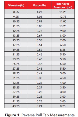
In both cases, one can convert the pull tab force to pressure by conducting a calibration experiment. Cut a cube of material away from the wound roll you just tested. Cut coupons to a known dimension (eg: 4” x 4”). Place a pull tab into this stack of material at the same distance it was previously inserted into the roll. Place a known amount of force onto the stack using static weights or a tensile frame with a compression load cell. Calculate the pressure exerted onto the stack (EG 160# / 16 in^2 = 10 psi). Use the same hand held load cell to remove the pull tab. Repeat this exercise for three loads that represent three interlayer pressures. Calculate a calibration coefficient to convert pull tab force to interlayer pressure. The relationship should be linear.
See Figure 1 for an example of the data collected and the resulting graph. For this example the calibration coefficient is 12. Pressure [psi] = Pull Tab # x 12 psi/#
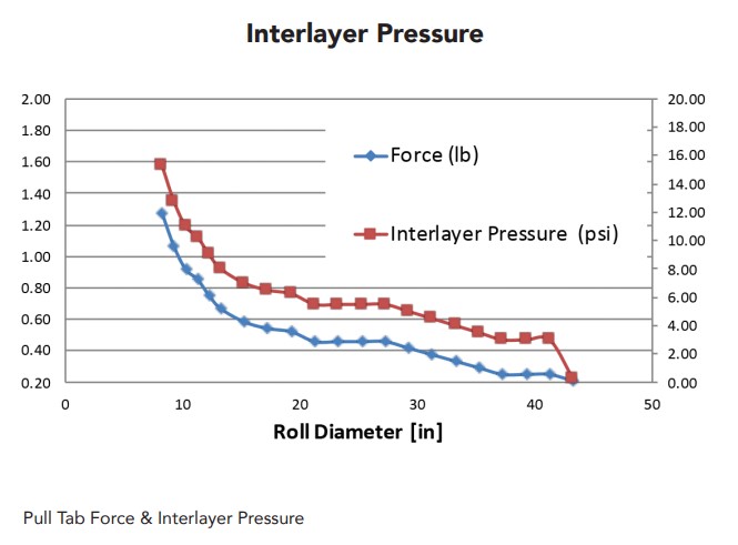
See Figure 2 for measurements that were taken from a sample 60” diameter roll of tissue. Note how the caliper is the inverse shape of the interlayer pressure. This is an example of a Soft roll structure. The S shape profile for interlayer pressure results in an inverse S shape relationship for caliper. See Figure 2.
Document Stored MD Strain
There are two proven ways to document your stored MD strain thru-roll:
- Measure repeating patterns on your web
- Print Registration marks before the Winder
If you have a repeating pattern (EG – registered graphics, embossing pattern) on your web you can often measure from one feature to the same repeating feature. Measure the roll circumference. Calculate roll diameter. Measure the repeat length on the roll. Strive to take the longest measurement possible. For example if your nominal repeat length is 12”, it is better to measure the distance of three repeating cycles (Ú 36” nominal). You may be looking for a difference of 1-2 percent stored strain difference. The longer repeat length will increase your resolution.
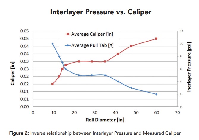
If your web does not have a repeating pattern, you can print one on the web before it enters the winding process. Figure 3 shows an installation of a printer and the subsequent registration marks.
It is important to use a nominal length that is as long as possible that will facilitate the length measurement on the roll. You should be able to measure to 1mm accuracy. Use a 250mm repeat pattern for 3” cores; 500mm for 6” cores and 1000mm for 20” cores. This will allow measurements all the way to the core.
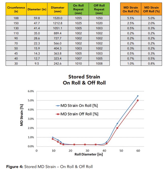
Figure 4 documents the Stored MD strain on roll and off for another roll of tissue. Note that the “off roll” measurements were taken by removing the sample from the roll. Lay it out on a smooth table to allow a second measurement. Off roll strain will be less than the on roll strain. The amount of difference is due to plastic deformation.
Document Average Wound Roll Density
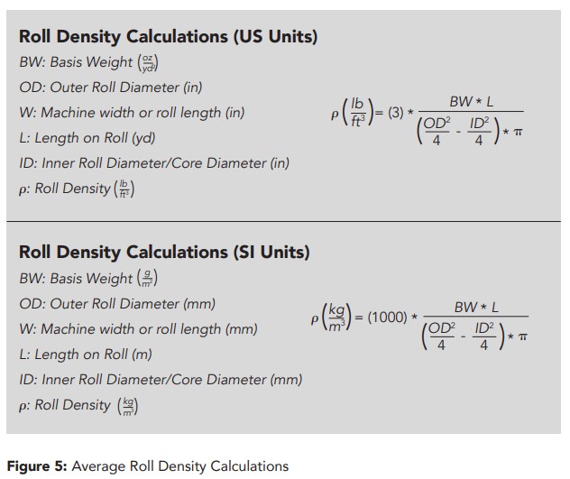
Average Wound Roll Density is a single metric that allows one to understand your wound roll structure. This is particularly true for compressible materials such as nonwovens, tissue and high loft webs. Although less sensitive, it is also a helpful metric for paper and film. You only need three parameters: Roll Diameter, Roll Length and Basis Weight. This information is typically on your roll ticket. If this data is stored in your PLC, you can begin to calculate this for every roll that you make. Figure 5 provides both US and SI units for calculating average roll density.
Next month we will discuss the important of tension, nip and torque for your winding process.
About the Author
Neal Michal of Converting Expert is a well-known authority in web handling, process design and optimization. He worked with the Web Handling Research Center for 20 years. Currently serving as a technical advisor with AIMCAL, he can be reached at This email address is being protected from spambots. You need JavaScript enabled to view it. or through www.convertingexpert.com