


Dancer Rollers: Trust but verify
- Published: November 01, 2006, By Timothy J. Walker, TJWalker & Assoc. Inc.
Web Lines
In last month’s tension quiz, I gave out five points if your process had a calibrated tension transducer roller. Those of you with dancer rollers might have wondered why you didn’t get any points. Why am I “dissing” dancers?
I like to know my web’s tension, and dancer rollers don’t tell you what the tension is or how much it varies. A dancer roller is not truly a tension feedback device. It doesn’t rise or fall because the tension is too high or too low. Dancers respond to errors in the speed ratio of the input and output web drives.
Besides not telling you what your tension is and how much it’s varying, the other big disadvantage of a dancer roller is that it will create tension variations. Every dancer roller has some resistance to motion, including friction and inertia (both translational and rotational). Tension decreases while accumulating and increases while dispensing.
So why are dancers popular? Dancers can accumulate or dispense, keeping tension variations low during speed-varying events such as out-of-round rolls, accelerating, uncoordinated drives, turret winder indexing, and transitions of zero speed splicers. In a dancer-controlled tension zone, if the input web speed is 0.2 in./sec (1 fpm) faster than the output, the dancer will accumulate the difference, collecting 1 in. of web for every second the speed differential exists. If a 0.2-in./sec speed differential occurs in a transducer roller zone, the web quickly will become slack or the tension will spike high.
Every time I see a dancer without a transducer roller in the same zone, I immediately start to calculate the web tension from geometry and air pressure. In many processes, the control panel may say you are setting the web tension, but in a dancer zone, all it really is controlling is the air pressure to the dancer assembly cylinders. You believe the control panel display for dancer tension if you trust the equipment designers and programmers.
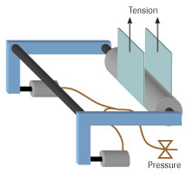
Here are the easy steps to estimate how the air pressure supplied to a dancer roller system creates web tension:
- Calculate the total area of the air cylinder(s) (e.g., 5 in.2 times 2 cylinders is 10 in.2
- Calculate the total air cylinder force output at 10 psi of air pressure (e.g., 10 psi x 10 in.2 = 100 lbf).
- Multiply this value by the dancer arm length and divide by the distance from the air cylinder to the pivot point (e.g., in this diagram, the leverage ratio is 1:2, so the effective cylinder force at the roller is 100 lbf x 0.5 = 50 lbf).
- For vertical dancers, add the roller’s weight to the leverage cylinder load (e.g., if the roller weight is 30 lbf, the combined roller load on the web is 30 lbf + 50 lbf = 80 lbf).
- For 180-deg wrapped, the two webs pull against the one roller, so web tension will be half of the combined roller load (80 lbf/2 = 40 lbf).
Timothy J. Walker has 20+ years of experience in web handling processes. He specializes in web handling education, process development, and production problem solving. Contact him at 651/686-5400; jwalker@tjwa.com; tjwa.com.