


Winding Part 3: Tension, Nip and Torque
- Published: January 17, 2023
By Neal Michal, Principal, Converting Expert, LLC
Winder TNTs are the key to winding a good roll. TNTs stand for Tension, Nip and Torque. Tension is the force in the plane of the web. Nip is the force applied against the building roll. Torque is an optional third parameter and is specific to the type of winder.
Tension is the most important factor for most winders. Nip is a close second for most materials. Torque will often extend the useful range of a winder.
A center winder only has tension. A lay on roller adds nip load to a center winder. By definition any surface winder will have both tension and nip. A surface winder with center wind assist adds torque to the coreshaft. Sophisticated belted reels also use all three TNTs to build large rolls with consistent properties. Now, let’s take a closer look at each TNT.
Tension
The three most common methods to establish tension is closed loop control using load cells, open loop control using an air loaded dancer and draw (velocity) control. Although not common, some winders run to a defined strain to control web registration. Older paper machine reels often used motors running in torque mode.
One should calculate tension if no load cells are in place. For a dancer system, solve for the force in the plane of the web based on cylinder area, air pressure and mechanical geometry. In order to calculate tension for draw control (or defined strain), one must have strain entering the winder and material modulus. Tension can be calculated for an older reel based on applied torque, gear train, friction losses and drum radius. Refer to my previous PFFC series on material testing regarding modulus and the equations required to calculate tension.
Nip
“Nip” implies nip load. It is important to understand how the nip load is generated. There are several dozen ways to provide nip load. It is best to sketch the process out and turn it into a statics diagram. One must solve for the force that is perpendicular to the building roll. Some OEMs are guilty of not providing the information required to calculate nip. Pressure in psi or nip loading in percent full scale is not nip load. One may be required to install pressure gauges or take direct measurements with load cells or in line force transducers. Please consider safety when documenting nip load on a commercial winder.
Torque
Torque is the force that can cause an object to rotate about an axis. Torque for a center assisted winder is straight forward. Document how much torque the motor applies to the coreshaft. If your winder uses magnetic particle clutches one will need to calculate torque based on the excitation voltage or current. If your winder uses differential shafts, one will need data from the OEM in combination with roll weight, percent slip, core width and dynamic coefficient of friction between the core and the shaft.
Wound On Tension “WOT”
Wound on tension or “WOT” is the combination of the TNTs that are being used. WOT is the tension in the outer lap entering the building roll. Dr. David Pfeiffer pioneered the use of a single drum pilot winder to measure WOT in the 1960s. Dr. Keith Good significantly extended this work at the Web Handling Research Center (WHRC). The WHRC WOT winder is shown in Figure 1. The author has conducted WOT studies on more than a dozen materials.
Figure 1 WOT Winder
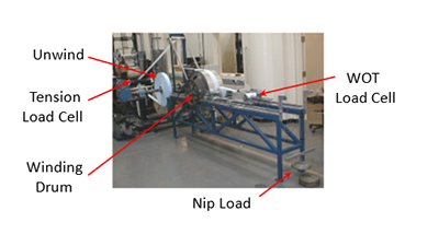
In both cases (Pfeiffer, Good) the combined effect of both tension and nip can be directly measured with load cells. Once the WOT winder is set up for a given material, a series of tests are made while tension and nip load are varied. Figure 2 shows how WOT varies as a function of eight decreasing nip loads (20.3 à 0.7 pli) with three tension levels (0.32, 0.28 & 0.18 pli).
Figure 2 WOT Raw Data
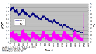
Figure 3 summarizes this data using intrinsic units of pli. The three curves represent high, medium and low tension. Note the wide array of settings where the process can be configured. Tension and nip work together.
Figure 3 WOT Graph
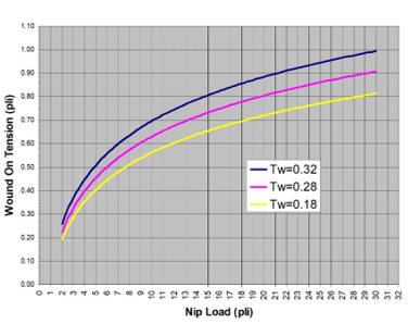
Note: This graph represents: Surface winder; 30” drum, web to web COF = 0.32, web to drum COF = 0.25.
The shape and magnitude of the graph will change as those parameters are altered.
Wound On Tension – Application
Using this info, the following combinations will provide the same Wound On Tension.
- Tension 0.32 pli + Nip 7 pli = 0.6 pli WOT
- Tension 0.28 pli + Nip 9 pli = 0.6 pli WOT
- Tension 0.18 pli + Nip 12 pli = 0.6 pli WOT
One can also determine what happens when tension or nip vary independently. Two real world examples will be provided. Assume Figure #3 applies for both cases.
Center Winder with Lay-on Roller
As the turret indexes forward it is common to see tension increase due to the change in length. That is why one will see a visible signature near the outside of the roll. Assume nip load is constant at 10 pli. Assume tension increases momentarily from 0.18 to 0.32 pli. WOT will increase from 0.55 to 0.70 pli. That represents a 27 percent increase.
Surface Winder
It is common to see double nip loading during the handshake between the first and second wind positions. This results in a “winder signature” which is a visual defect but can cause converting issues if your customer runs to the core. Assume tension is held constant at 0.18 pli. Assume nip loading momentarily spikes from 3 to 6 pli. WOT will increase from 0.30 to 0.42 pli. That represents a 40 percent increase.
In closing, controlling the TNTs is key to building a good roll. Tension and nip work together. Every winder has known limitations based on their design and how they are controlled. It is important to determine what the actual tension, nip and torque will be for the entire duration of the winding process. If you control your TNTs, you will improve delivered quality to your customer.
Stay tuned for Winding Part 4 where we will discuss best practices that will improve productivity, safety and delivered quality.
ABOUT THE AUTHOR
Neal Michal of Converting Expert is a well-known authority in web handling, process design and optimization. He worked with the Web Handling Research Center for 20 years. Currently serving as a technical advisor with AIMCAL, he can be reached at neal@convertingexpert.com or through www.convertingexpert.com.


