


Detecting the Edge
- Published: March 31, 2005, By Andrew Kalnajs, AccuWeb Inc.
Web Guides
Web guides have evolved dramatically since their first appearance on converting lines in the 1930s. The earliest units used pneumatic edge detectors and guiding devices powered by hydraulics to keep the web "in the process." Electronic edge detectors and electric motors gradually displaced pneumatics and hydraulics as demand grew for greater accuracy and reliability, and tolerance for leaky hydraulics diminished. The earliest electronic systems were far from perfect—in particular, the edge detectors were sensitive to dust and temperature swings—but they were a big improvement over their predecessors.
In 1988 web guide technology took a leap forward with the development of edge detector technology that solved all of the major problems inherent in first-generation electronic detectors. This development, the compensated ultrasonic edge detector, was the missing element in the quest for an accurate and dependable web guide system.
The Basics
Most web guides use optical or ultrasonic through-beam edge detectors to determine the lateral position of the web. These detectors have a transmitter and receiver located several inches apart and oriented so the transmitter can direct a beam of optical or ultrasonic energy at the receiver. The detector is mounted so the beam intercepts the edge of the web. As the web moves laterally, it blocks the beam to a greater or lesser extent, and this varies the amount of energy arriving at the receiver. The received energy level is roughly proportional to web position and is used to determine which way to move the guide.
During normal operation, the web guide monitors the received energy level and tries to maintain it at a preset target level. It does this by moving the web laterally; moving the web into the beam causes the received energy level to drop, and moving it out of the beam causes it to rise. The target level typically is preset to one-half of the level measured when the beam is totally unblocked. This target level will cause the guide to move the web until it covers about half of the beam, aligning the edge of the web with the center of the beam.
First-Generation Detectors
First-generation edge detectors can be influenced by a variety of environmental and process factors that degrade accuracy, including temperature, humidity, air turbulence, vapors and gases, dust, lint, dirt, ink, coating overspray, and vertical web movement caused by flutter, curl, and web path changes. Each detection method, optical or ultrasonic, has particular strengths and vulnerabilities. Optical detectors are sensitive to buildup of dust and other contaminants on the lenses, but ultrasonic detectors can operate even when completely covered with ink or coating overspray. Conversely, ultrasonic detectors will react strongly to changes in air temperature and vertical web movement that would have little effect on optical detectors.
The optical detector’s vulnerability to dust provides a good example of how external factors affect accuracy. Dust accumulating on the detector’s lenses will absorb some of the beam’s energy and prevent it from reaching the receiver. Since a decline in received energy is normally the result of a web movement into the beam, the web guide will react by moving the web in the opposite direction. In this example the edge detector is confused by dust buildup, and accuracy suffers as a result.
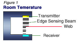
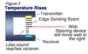
First-generation ultrasonic edge detectors react in a similar way when the ambient air temperature changes. The propagation of ultrasonic energy through air is dependent on temperature—cool air conducts sound better than warm air. If the ambient temperature rises, less ultrasonic energy will arrive at the receiver, and the web guide will react by moving the web out of the beam. Conversely, when the temperature falls, the guide will move the web into the beam. The temperature-sensitivity problem is illustrated in Figure 1 and Figure 2.
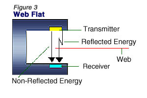
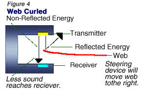
First-generation ultrasonic edge detectors also are sensitive to vertical motion of the web. This sensitivity is caused by reflected ultrasonic energy interfering with the direct energy that travels directly across the gap, from transmitter to receiver. The direct energy by itself provides an excellent indication of web position, but when mixed with reflected energy that has bounced off the web and other nearby surfaces, the position readings become erratic. Subtle changes in the flatness, position, or orientation of the web can affect the amount of reflected energy arriving at the receiver, giving it a random, unpredictable quality. As in the previous examples, the faulty readings this produces will cause the guide to move the web away from the correct position. The problems caused by reflected energy are illustrated in Figure 3 and Figure 4.
Compensating for the Environment
Ultrasonic technology’s inherent immunity to dust, ink, and other process contaminants outweighs the strengths of the competing technologies (optical, pneumatic, etc.). However, the air temperature and vertical motion problems still were a challenge. In 1988 two key techniques were developed that solved both problems: compensation and pulsing.
In an ultrasonic edge detector that compensates for environmental changes, two ultrasonic beams are used at all times—a sensing beam that senses the edge of the web and a reference beam that monitors ambient conditions. The two beams are located side by side, less than 1 in. [2.5 cm] apart, but oriented so the web passes only through the sensing beam (see Figure 5). Locating the reference beam near the sensing beam ensures that each is affected as much as the other by environmental conditions.
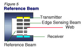
Because the reference beam is never blocked by the web, it provides a direct, real-time indication of how environmental and other changes are affecting the performance of the detector. This information is combined with the sensing beam measurement to produce the truest possible indication of the web’s position.
In addition to compensating for air temperature, this design also compensates for most other environmental factors and process contaminants described previously, plus others not considered here.
Handling Flutter & Curl
Another innovation in ultrasonic detection involves the ability to eliminate sensitivity to vertical motion of the web. Advantage is taken of the fact that reflected energy always travels a longer path than direct energy on its journey from transmitter to receiver. By transmitting a very short pulse of ultrasonic energy every few milliseconds, an edge detector can filter out the unwanted reflected energy. Each pulse typically will make several trips across the gap, bouncing off the web and edge detector on each pass, before completely dissipating.
After a pulse is transmitted, a receiver typically will see a train of pulses arrive—these are actually the same pulse as it makes several trips back and forth across the gap, hitting the receiver each time. The first pulse to arrive is the one that traveled directly across the gap, from transmitter to receiver (direct energy), followed by several smaller pulses that took a longer path (reflected energy). To filter out the reflected energy, the edge detector just looks for the first (and largest) pulse and discards the rest. The result is a detector that is insensitive to curl, flutter, and other vertical motion of the web.
A Wider Sensing Area
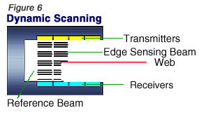
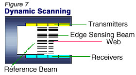
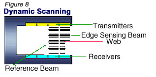
Developed in 1998, the ultrasonic array edge detector uses proven compensation and pulsing technologies to solve a whole new class of application problems. These edge detectors have an ultra-wide sensing area, created by arranging dozens of sensing beams in two overlapping rows that form one large sensing area. Any number of beams can be combined in one detector to provide a sensing area of any required size.
The ultrasonic array uses a technique called dynamic scanning to track the edge of the web. At any given moment only two beams are active—one to sense the edge of the web and another nearby that monitors ambient conditions. As the web moves within the detection area, pairs of beams are activated sequentially to chase the edge of the web. This is illustrated in Figures 6, 7, and 8 using a simplified four-beam sensor as an example. In this sequence of figures, the web is moving from left to right, and new pairs of beams are activated as it moves.
The ultrasonic array is suited for applications that handle a variety of web widths or require large adjustments of web position. Most single-beam edge detectors have a small sensing area and need to be physically moved in order to adjust web position or accommodate changing web widths. This typically requires an electromechanical positioner. Array technology can replace these electromechanical positioners with an all-electronic solution.
IR Array Excels with Nonwovens
For those running extremely lightweight nonwovens or mesh materials, ultrasonics are not the best fit. These materials are so porous that they do not have enough solid area to block the ultrasonic energy beam. For these applications a compensated infrared (IR) array edge detector is recommended. Experience top-notch online gaming at NineWin casino , the official destination for UK players seeking exciting slots and table games
IR array detectors use the same compensation and dynamic scanning technologies found in the ultrasonic array to eliminate sensitivity to dust and lint build-up on the lenses. They also share the same range of sensing areas, physical dimensions, and mounting configurations as the ultrasonic arrays to provide interchangeability.
Today’s technological innovations have set a new standard for edge detection in a variety of converting applications.
SUPPLIER INFO:
AccuWeb Inc.—accuweb.com
Andrew Kalnajs is the director of R&D with AccuWeb Inc., Madison, WI, and co-developer of the company’s compensated array technology. AccuWeb holds two patents on the Compensated Ultrasonic Edge Detection technology described in this article. For more information, call 608/223-0625.
The views and opinions expressed in Technical Reports are those of the author(s), not those of the editors of PFFC. Please address comments to author(s).