Quick Roller Alignment Check
- Published: August 21, 2020

By Tim Walker, Contributing Writer
Most converters understand the importance of roller alignment and related problems. Misalignment as small as 0.020 in. (0.5 mm) can lead to web wrinkles. Troublesome equipment errors are usually invisible to the unaided eye. To detect, correct and maintain good roller alignment requires tools beyond a hardware store bubble level and tape measure, but may not require the expense and downtime of the most sophisticated tools.
Many converters appreciate moving up to better than hardware store tools, such as a precision level that indicates perpendicularity to gravity in units of 0.5mm/m or 0.005 in./ft. For 1.25m (60 in.) wide equipment, this can measure absolute errors of 0.6mm or 0.025-in (less than 10 sheets of paper). Precision levels work great for the vertical errors of your equipment and rollers, but another tool is needed for the horizontal or other non-vertical web spans. The quick tools for non-vertical alignment are:
- Tramming sticks; and
- Pi tapes.
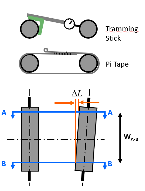
Pi tapes are commercially available and commonly used to measure roller diameter and cross-width diameter profile. They are less frequently used for checking roller parallelism. Instead of using the pi tape to measure diameter, wrap the pi tape around two rollers creating a two-roller belt of the combined two spans and two roller wraps. As pi tape measurements are designed to read diameter directly and this method measures the alignment error twice, the pi tape readings need to be divided by 1.57. Alignment is found from the difference in this two-roller belt perimeter from one side to another.
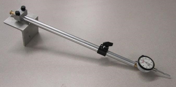
Tramming sticks are less common that pi tapes. Though there are snap gauges and other internal measurement methods, they are not directly applicable to measure a two-roller alignment. Strangely, this useful technique is not commercially available. All the tramming sticks I have used are ‘home-made.’
 Tramming sticks have three components:
- A dial indicator measuring 0.001-in. increments over a 1-in. range (25 micron over 25 mm);
- A telescoping rod; and
- A crow’s foot or angle iron to hold the device square to the reference roller’s cylindrical surface.
To measurement roller-to-roller alignment, set the crow’s foot on one roller, extend the telescoping rod to contact the second roller’s face within the range of the dial indicator. Measure one side of the two rollers by sweeping the tramming stick up and down noting the shortest distance. Find the misalignment by repeating this measurement on the other side of the roller, noting the side-to-side difference.
These two corrections, level followed by in-span parallelism (tram) will make for a happier web. But for best long-term results, these two steps should be part of a larger alignment strategy. Before these two steps, your plan should include:
- Ensuring your foundation is reliable (solid earth, sufficient concrete);
- Select reference roller or establish centerline monuments;
- Center rollers on machine centerline (this step is helpful, but not required);
- Use a sole plate on top of the concrete as a base to rest large equipment stations; and
- Ensure rollers are cylindrical using a pi tape, as any errors here will throw off our level and squareness measurements.
With these preliminary steps compete, you can move to precision level and tramming. If you are happy with how the web runs and want it to continue to do so, consider locking roller alignment by drilling and pinning the roller mounts in place.
There are more expensive and more accurate tools to measure roller alignment, including optical, laser and laser gyros, but for quick checks (and lower cost) the stick tram can be your first line of defense again roller alignment errors and their related waste.
About the Author:
Timothy Walker authors Web Lines, a column devoted to web handling, winding, guiding, rollers, and more. He has 35 years of experience in web handling processes. He specializes in web handling education, process development and production problem solving.


