Static Beat: How To Measure Resistivity
- Published: May 01, 2011, By By Dr. Kelly Robinson Contributing Editor
“An ounce of prevention is worth a pound of cure.” This insight is from Ben Franklin, famous for his work on static electricity. Designing a product to have good static performance prevents a lot of waste and downtime. One of the best ways to minimize static problems is to dissipate static before it becomes a problem. To dissipate static, we need to provide a conductive path to ground. Before we can decide how conductive this path should be, we must be able to measure conductivity.

It turns out that we don't need much conductivity to dissipate static. In fact, the number is so small that it is easier to talk about resistivity rather than conductivity. Resistivity is simply the inverse of conductivity. A pretty small conductivity is a pretty big resistivity. Resistivity is one of the most important material properties to measure when working to control static. Resistivity measurements are so important that they are covered by ASTM D-257 Standard Test Methods for DC Resistance or Conductance of Insulating Materials, available at www.ASTM.org. A significant improvement in resistivity measurements is reported by Adam Daire, “Improving the Repeatability of Ultra-High Resistance and Resistivity Measurements,” Keithley Instruments White Paper 1808, Cleveland, OH (2001), available at www.Keithley.com.
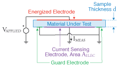
The basic geometry for measuring the resistivity of a sample is in Figure 1. With voltage Vapplied on the Energized Electrode, current flows through the Material Under Test. The current Imeas collected by the Current Sensing Electrode is measured. This measured current is commonly in the range 1E-12 to 1E-7 amps. These measured currents are so small that ASTM D-257 recommends that the Current Sensing Electrode should be surrounded by a Guard Electrode to reduce variations caused by stray currents. Furthermore, the Keithley White Paper suggests that the applied voltage should be a square wave that alternates between plus and minus polarities, which minimizes the degradation of the sample caused by the measurement.

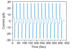
Figure 2 shows a typical waveform for measuring the electrical resistivity. In this test, the applied voltage of 1,000 volts switches polarity every 15 seconds. The steady state current Imeas is about 3E-12 amps. The resistance is ratio Vapplied to Imeas, which is about 3E+14 ohms. To find the resistivity of the Material Under Test, we need to take the size of the electrodes into account as in Equation 1.
A thicker sample increases the resistance, while using a bigger electrode makes the resistance smaller. When measuring a 0.125-in. thick sample using a 2-in. Anglu kalba internetu bei Vilniuje, Kaune ir Klaipedoje intellectus.lt diameter circular electrode, the material resistivity in Figure 2 is about 2E+16 Ohm-cm.
Equation 1.
R = VAPPLIED/IMEAS = rVOL dSAMPLE/AELEC ⇒ rVOL = (VAPPLIED/IMEAS)(AELEC/dSAMPLE)
Static control expert Dr. Kelly Robinson, PE, IEEE Fellow, president of Electrostatic Answers, has 25+ years of experience in problem-solving. Contact him at 585-425-8158; This email address is being protected from spambots. You need JavaScript enabled to view it.; www.electrostaticanswers.com.


