Static Beat: Surface Resistivity Testing
- Published: June 01, 2011, By By Dr. Kelly Robinson Contributing Editor
Designing products to have good static performance is cheaper and more reliable than upgrading manufacturing lines so they can handle static-prone products. Good product designs sure beat traveling to customer sites to solve frustrating problems.
To dissipate static, we need to provide a conductive path to ground. However, making an insulating polymer even a little bit conductive is a big challenge.
One good strategy comes from realizing that static charges are only on the surfaces of polymer films, so we need conductive paths only on the surfaces of our polymers. A number of antistatic additives for polymers are available that provide a low level of surface conductivity, and coatings can be formulated to provide some conductivity.
Of course, to dissipate static, we don't need very much conductivity. In fact, the numbers are so small that it is easier to talk about surface resistivity, which is the inverse of surface conductivity.
Before we can determine what surface resistivities are needed for our products, we need to measure surface resistivity in a consistent and repeatable way. Surface resistivity measurements are so important that they are covered by ASTM D-257 Standard Test Methods for DC Resistance or Conductance of Insulating Materials, available at www.ASTM.org.
A significant improvement in resistivity measurements is reported by Adam Daire, “Improving the Repeatability of Ultra-High Resistance and Resistivity Measurements,” Keithley Instruments White Paper 1808, Cleveland, OH (2001), available at www.Keithley.com. The alternating polarity method described in Keithley White Paper 1808 applies to surface resistivity measurements.

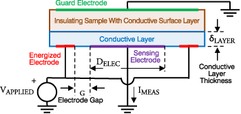
The surface resistivity of the sample in Figure 1 is determined by measuring the resistance (RMEAS) between a grounded circular electrode and an energized concentric ring electrode that both touch the conductive layer. To measure the resistance, apply voltage (VAPPLIED) to the ring electrode and detect the current (IMEAS) that flows through the Conductive Layer to the circular Sensing Electrode. This current can be very small, commonly in the range of 1E-12 to 1E-7 amps, so ASTM D-257 recommends using a Guard Electrode to reduce variations caused by stray currents.
The volumetric resistivity (rVOL) of the conductive layer is found from the measured resistance (RMEAS) in Equation 1 where AMEAS is the cross-sectional area of the current path.
We almost never talk about the volumetric resistivity of a thin layer because the thickness (dLAYER) in Equation 1 is often so small (perhaps only a few molecules thick) that it is difficult to measure. One practical way to avoid this problem is to define surface resistivity (rSURFACE) in Equation 2.
Equation 2.
Now the surface resistivity (rSURFACE) can be found in terms of easily measured parameters, and it is a good measure of static performance because surface resistivity determines how fast static charge will dissipate from our film. While the formal units of surface resistivity are ohms, the practical units of ohm/square have been adopted to distinguish surface resistivity from the resistance (RMEAS).
The resistance (RMEAS) should be measured carefully because it can be quite large. RelaxInfo With an applied voltage of 1,000 V and a current (IMEAS) of 10 pA, RMEAS is 1E+14 ohms. Using a Sensing Electrode with a diameter (DELEC) of 50 mm with a ring electrode that forms a Gap (G) of 3 mm, the surface resistivity of our sample would be 5.6E+15 W/sq.


Static control expert Dr. Kelly Robinson, president of Electrostatic Answers, has 27+ years of experience in problem-solving and consulting. Contact him at 585-425-8158; kelly.robinson@electrostaticanswers.com; www.electrostaticanswers.com.


