


Featured Stories
-

The Importance of Roll Cleaning and Maintenance
A question-and-answer with Joe Walczak, President of Sonic Solutions. -

Leveraging New Technology for Advancements in Battery Electrode Manufacturing
Machine designers and process engineers in the battery industry are witnessing a pivotal shift towards more space-efficient, precise and... -

Advantages of Shear, Razor and Crush Web Slitting Techniques
When choosing a slitting method, many factors must be considered, including interaction with inspection systems.
News | New Products
-
GMG Color Americas to showcase next-generation color management solutions at FTA FORUM & INFOFLEX 2025
GMG Color, a global leader in color management and proofing solutions, announces its participation in the FTA FORUM & INFOFLEX 2025
-
Kongsberg Precision Cutting Systems Launches IPC 3.1 For Faster, Smoother Table Operations
Kongsberg Precision Cutting Systems (PCS) has launched the latest version of its table operating software IPC 3.1.
-
EFI Showcases Latest Solutions Expanding the Possibilities of Digital Printing at the ISA International Sign Expo
Electronics For Imaging, Inc. (EFI™) is showcasing its newest hybrid and flatbed LED inkjet printers at the ISA International Sign Expo® in Las Vegas, April 23-25.
-
EMT International Expands Cutting Technology Portfolio with slittec Partnership
Strategic Alliance Enhances EMT's Comprehensive Slittling Solutions for Paper, Film and Packaging Industries
-
BW Converting Highlights Hudson-Sharp Pouch Machines at Petfood Forum 2025
Driving innovation in pet food packaging with high-performance bag and pouch converting machines
-
Mark Andy Sponsors 2025 Phoenix Challenge College Competition Advancing Workforce Development and Industry Engagement
Mark Andy, a global printing and labels solutions company, continues its support of the Phoenix Challenge
-
Cards & Systems Solutions Invests in Rollem InsigniaX3 to Expand In-House Die-Cutting Production
Cards & Systems Solutions, a leader in the manufacturing of plastic cards and comprehensive fulfillment services, has received a successful installation of the Rollem InsigniaX3 Rotary Die Cutter.
Expert Advice


Static Beat | Assess Static Risks Using Electric Fields
- Published: May 13, 2019
Fieldmeters have been available for over 80 years dating back to at least 1936 when the General Electric Company patented an electrostatic field mill device having rotating vanes (US 2,032,932). The interest back then was measuring the electric fields near high voltage power lines. These very sensitivity field mills are commercially available (see, for example the JCI 140) along with the closely related vibrating sensor fieldmeters (see, for example the Monroe 257D). Newer and more economical electrometer / capacitive sensor fieldmeters are also available (see, for example handheld electrostatic fieldmeters). Even with our 80-year experience using electrostatic fieldmeters, assessing static risks remains challenging. To assess static risks, we must first understand what our readings mean.
First, I acknowledge and thank three of my colleagues for helping me understand fieldmeters, how to use their readings, and their insights that I offer here to you.
- Jeremy Smallwood, Electrostatic Solutions Ltd
- Bill Vosteen, President, Monroe Electronics
- Al Seaver, Electrostatics Consultant
Assess static risks by looking at the electric fields measured by our fieldmeters. The confusion is that many static meters display readings in volts rather than field. Electric field are measured in volts per distance. KV/in or KV/cm are common units. To assess static, convert your static readings into electric fields. To do this, use equation 1 and divide the static meter reading in KV by the measurement distance DMEAS.
 (Eq. 1)
For example, if your meter reads +5 KV at a measure distance DMEAS of 1 inch, the nominal electric field ENOMINAL is +5 KV/in.
Assess static risks using the Static Stop Light Levels in Table 1 once you know the electric field.
Table 1: Static “Stop Light” Levels
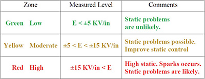
The industry standard “5,000 Volts rule” (see A. Seaver, “Analysis of electrostatic measurements on non-conducting webs,” Journal of Electrostatics, Vol. 35, 1995) defines the “Green Zone” where static levels are low and sparks are highly unlikely. My experience is that sparks are likely in the “Red Zone” where static is high. In between these two zones is the “Yellow Zone” where static is moderate and static control should be improved to get the readings into the “Green Zone.”
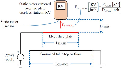
Figure 1: The static meter is calibrated to display the voltage of a conducting plate.
Let’s take a closer look at static readings. The static meter in Figure 1 detects the electric field at its sensor. For converting applications, the meter would be more useful if it displayed the nominal electric field in KV/in or KV/cm. However, many static meters are calibrated to display the voltage of the conducting plate. For example, when the power supply in Figure 1 is set for +5.0 KV, the static meter displays +5.0 KV when it is held at the recommended measurement distance DMEAS. Of course, the plate size LPLATE must be much larger than the measurement distance DMEAS so that the static sees only the plate and not the grounded surface below, which might be a table top or perhaps the floor.
When calibrating the meter in Figure 1, the nominal electric field detected by the meter in Eq. 1 varies as 1/DMEAS, which makes this measurement distance very important.
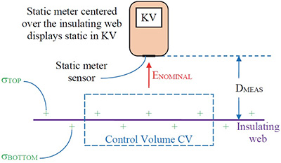
Figure 2: We use static meters to detect the static on insulating webs.
In converting operations, we use the static meter in Figure 2 to detect the static charges on the insulating web. Insulating webs are different from conducting plates. The nominal electric field ENOMINAL in Eq. 2 detected by our meter in Figure 2 is proportional to all of the electrical charges inside control volume CV.
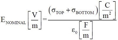
(Eq. 2)
The constant e0, the permittivity of free space, is 8.85×10⁻¹² F/m or 8.84 pF/m. So, if our web has a charge density of +2.0 mC/m2, (+2.0×10⁻⁶ C/m2), the electric field would be 2.3×10+5 V/m, which is 2.3 KV/cm or 5.7 KV/in. So, a charge density of +2 mC/m2 on our web is just enough static to move the fieldmeter reading out of the “Green Zone” and into the “Yellow Zone.”
The electric field near an insulating web is different from the field near an electrified plate in two important ways.
- The electric field near our insulating web is the same whether we measure from the top or from the bottom of the web. Both readings are proportional to the sum of the charges on both surfaces. So, we can pick either surface. Choose the one to measure that is easier and safer.
- The electric field near our insulating web is nearly constant and does not change strongly with the measurement distance DMEAS. So, if we hold the meter at a distance that is a little bit different from the recommended measurement distance DMEAS, our reading will still be accurate.
Assess static risks using electric field calculated by dividing the static reading by the measurement distance. For example, if your meter reads +5 KV at a measure distance DMEAS of 1-inch, the nominal electric field ENOMINAL is +5 KV/in. Then, use the “Static Stop Light Levels” in Table 1 to assess static risks.
Please feel free to contact me if you have any questions or if you would like additional information. My email address is: Kelly.Robinson@ElectrostaticAnswers.com.


